Implementing EKMA: Step 4
There are two variations for the fourth step of implementing EKMA, the first requiring only the generation of a single set of isopleth diagrams, the second requiring the generation of a second set of diagrams. Single day-specific procedures are used when the non-emission conditions are not expected to change; as such, single sets of isopleths are not useful if any of the following situations are expected:
- ozone transported into the are changes
- precursors transported into the area changes
- the diurnal (daytime) emission pattern changes significantly
The second situation is when there are concurrent changes in emissions or other factors. In this case, an isopleth needs to be generated for the base case and for the future case, sometimes referred to as the post-control period.
Both situations are discussed below in greater detail.
Single Day-Specific Scenario Calculations
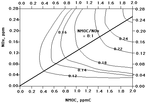
Perhaps the easiest way to describe the use of a generated isopleth and the calculations involved is with an example. In the example below, the modeler has determined that the daily design value (the maximum average hourly ozone concentration for the modeling site) has a value of 0.24 ppm. S/he has also determined that the design ratio, the ratio of VOCs to NOx, has a value of 8:1. A determination is made that there is an expected decrease in NOx of 20%. The task is to find the percentage of reduction of VOCs needed to reach an air quality standard of 0.12 ppm, the current NAAQS air quality standard:
- Given:
- O3 Daily Design Value = 0.24 ppm
- Design VOC/NOx = 8:1
- Anticipated change in NOx= -20%
- Base case isopleth diagram (below)
- Find: percent reduction in VOC emissions needed to reduce ozone from 0.24 ppm to 0.12 ppm
- Solution:

- Step 1: the base case point is found by the intersection of the 8:1 VOC/NOx ratio line with the 0.24 ozone isopleth. At this point, VOC1 = 1.62, and NOx1=0.20
- Step 2:The post-control NOx coordinate is calculated:
NOx2= (0.20) x (1-20/100) = 0.16
- Step 3:The post-control point is located at the intersection of the 0.16 NOx coordinate and the 0.12 ppm ozone isopleth. At this point, VOC2 = 0.40
- Step 4: the VOC emission reduction is calculated as:
% reduction = (1-0.4/1.62) x 100 = 75.3%
On the OZIP Web interface form, the modeler can create a single simulation without the inclusion of future changes and/or concurrent changes.
Concurrent Change Scenario Calculations
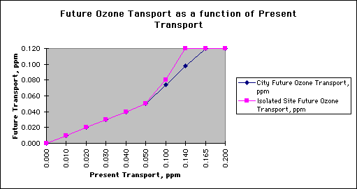
It may be the case that there exists a decrease in the amount of ozone aloft transported into the column of air. This "future" decrease may be the result of several factors, such as a reduction of ozone upwind of the modeling site as a result of control technologies applied upwind.
The graphic below is provided as a guide to estimating the future transport of ozone into the modeling site as a function of the present transport value of ozone aloft:

A JavaScript calculator is provided for use in calculating a future ozone transport aloft value for use in the OZIP model.
Back to Implementing EKMA


Developed by
 The Shodor
Education Foundation, Inc.
Copyright © 1997


 The Shodor
Education Foundation, Inc.